
Solids mass flow measurement up to 20 t/h
Continuous mass flow measurement of all types of dust, powder and granules in free fall and pneumatic conveying
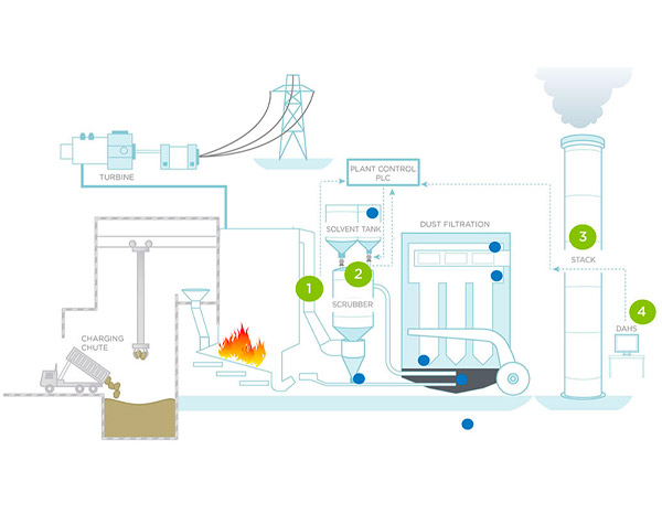
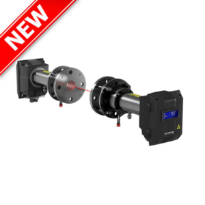
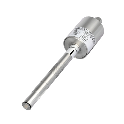
Microwave sensor for on-line mass flow measurement of solids up to 20 t/h.
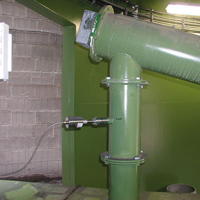
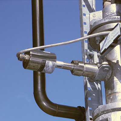
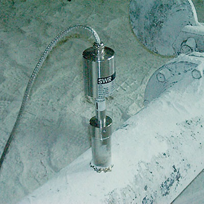
Used in pneumatic leanphase conveying or vertical freefall after mechanical feeders.
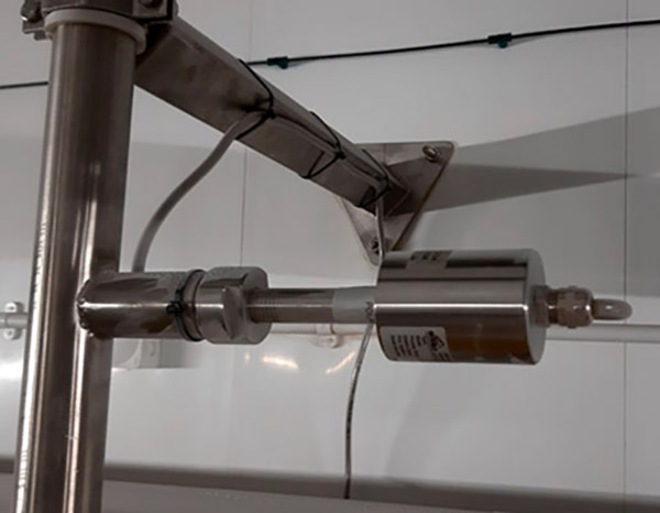
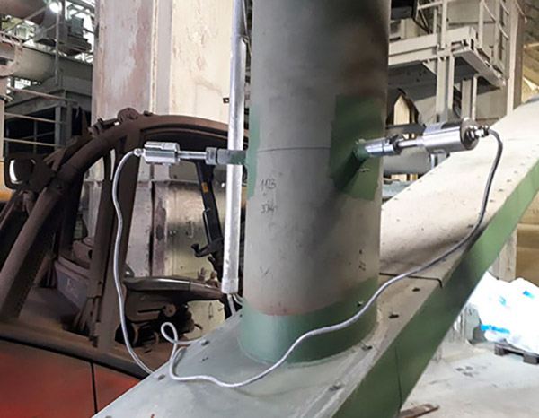
- easy installation via weld-on socket
- for almost all types of dusts, powders, granules
- uses field-proven technology with active roping compensation
- suitable for nearly all pipe diameters
Measurement for flow rates up to 20 t/h
- Features & Benefits
- Main applications
- Technical Specifications
- Technical Data
- Mounting Installation
- Downloads
- Simple retrofitting using a welding socket
- ATEX-certified
- Almost all types of dust, powder and granules can be measured
- No installations in the material stream
- Measuring principle: Microwave
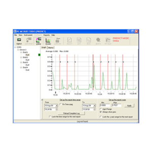
- Online flow metering
- Throughput measuring flowrates up to 20 t/h
- Active roping compensation for highest reliability
- Wear-resistant
- Biomass
- Cement
- Chemistry
- Coal plant
- Coating
- Food
- Incineration
- Minerals
- Wood
- Lime plant
- Energy
- Gypsum
- Power plant
- Foundry
| Technical Specifications | |
|---|---|
| Material to measure | Dust, powders or granulates max. grain size 20 mm |
| Working principle | Microwave |
| Process pressure | 1 bar, optional 10 bar |
| Process temperature | +200°C, optional up to +900°C |
| Mounting | Via process connection |
| Type of Conveying | Pneumatic leanphase, vertical freefall after feeder |
| Flow rates | Up to 20 t/h |
| Pipe diameter | Max. 800mm |
| ATEX rating | Category 1/2 |
| Output | 4…20mA, Modbus, Profibus |
SolidFlow 2.0 is a sensor especially developed for measuring the flow rate of solids conveyed in metallic ducts.
It has successfully been tested for online-measuring of:
- all types of dust, powder and granulates
- grain size between 1 nm and 1 cm
- pneumatically conveyed materials or
- in free fall after mechanical conveying systems
- SolidFlow is wear-resistant and the commissioning is very easy.
| Sensor Technical Data | |
|---|---|
| Housing | Stainless steel 1.4571 |
| Protection category | IP 65, DustEx zone 20 or GasEx zone 1 (optional) |
| Operating temperature | Front end of sensor: -20… +80 °C Optional: -20 … +200 °C Sensor electronic: 0 … +60 °C |
| Max. working pressure | 1 bar, optional 10 bar |
| Working frequency | K-Band 24.125 GHz, ±100 MHz |
| Transmitting power | Max. 5 mW |
| Weight | 1.3 kg |
| Dimensions | Ø 60, Ø 20, L 271 mm |
| Accuracy | ± 2 … 5 % in calibrated range |
| Transmitter Technical Data | ||||
|---|---|---|---|---|
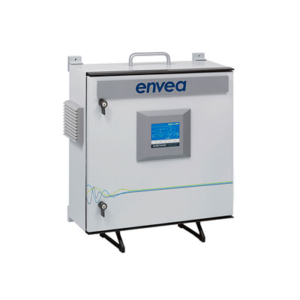
| Transmitter (DIN Rail) | Transmitter (field housing) | |||
| Power supply | 24 V DC ±10 % | 110 / 230 V AC 50 Hz (optional 24 V DC) |
||
| Power consumption | 20 W / 24 VA | |||
| Protection type | IP 40 to EN 60 529 | IP 65 to EN 60 529/10.91 | ||
| Ambient operating temperature | -10 … +45 °C | |||
| Dimensions (W x H x D) | 23 x 90 x 118 mm | 258 x 237 x 174 mm | ||
| Weight | Approx. 172 g | Approx. 2.5 kg | ||
| Connection terminals cable cross-section |
0.2-2.5 mm2 [AWG 24-14] | |||
| Current output | 1 x 4 … 20 mA (0 … 20 mA), load < 500 Ω |
3 x 4 … 20 mA (0 … 20 mA), load < 500 Ω |
||
| Interface | RS 485 (ModBus RTU) / USB | |||
| Pulse output | Open collector – max. 30 V, 20 mA | |||
| Relay contact | Max. rated load: 250 V AC Max. peak current: 6 A Max. rated load 230 V AC: 250 VA Max. breaking capacity DC1: 3/110/220 V: 3/0.35/0.2 A Min. switching load: 500 mW (10 V / 5 mA) |
|||
| Data backup | Flash memory | |||
| DIN rail fastening DIN 60715 TH35 |
Cable screw connectors 3 x M20 (4,5 – 13 mm Ø) |
|||
|
For the assembly of the sensor, the installation location is specified in accordance with the conveyed inlet and outlet paths. Commissioning: |
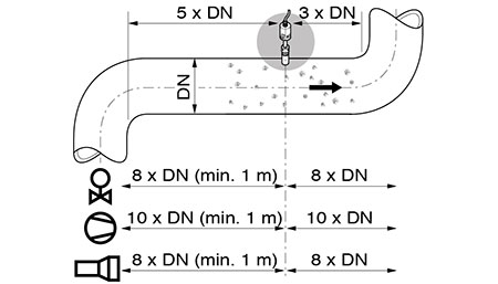 |